SW+ Project Build - Stage 1 Identifying the parts
Build instructions by Paul M0BMN
< Previous Next >Stage 1 Identifying the parts
In this stage i will show a few photos of how to identify the parts and how to fit them, these are here to help those that have not built anything before and experienced builders will probably be happy to skip over most of this im sure. You don't need to follow all these instructions if you are happy about doing something they are only here to help people that want a little extra help
Right Now you have got your kit and your ready to go , or are you!
make sure you have plenty
of light, you will need it to read the values on the parts, a Magnifying glass
is a great help here, i have a cheap one that as a light built into it that
i find fit for the job. You also need a small pointed soldering iron, the type
you heat up in the gas fire are not what we want here!, I recommend a good pair
of flush cutters to trim the components leads after you have soldered them.
Next a word on solder,
I use a 60/40 lead tin mix made by mulitcore but any similar stuff will do,
if your buying it for the first time then look for some around 0.5-0.6mm dia
stuff.
Now onto building, first read the Instructions from front to back, next read the instructions from front to back, yes read them twice .
Now find something like the foam that gets used in flower arranging, or even polystyrene packing will do, failing that a number of paper cups.
we need to make sure that we have all the parts before we start, open the bag with the resistors and capacitors in and look at the values, if you have a multimeter confirm the values of the resisters as we do the next step,
pick up the resisters one by one, you will note that they have multicolored bands, these bands can be decoded to tell you the value for example the first resistor is R6 that we will need to fit, this is 10 ohms, the coloured bands would be Brown , Black , Black. Brown=1 Black =0 Black=0 that means the value is 10 and the third band being black means Zero which is the multiplier to be applied to the value so if we find a Brown,Black,Red resistor we have the following
Brown = 1
Black = 0
Red = Multiply by 100
so we have 10 * 100= 1000 Ohms or 1K
here is a chart that may help with this
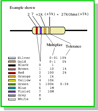
Don't panic if you are having problems, if you use your multimeter set to ohms you can read the values that way or if you look at the instructions part list it tells you what colour each resistor is, the resistor all have a 4th band too, this is to do with the accuracy of the value indicated and we need not worry about that in this design.
Now you can identify each resistor (don't confuse them with the 3 small inductors in a separate bag that look like "Fat" resistors) we need to check we have all of them for this kit, get a clean piece of paper and write down R1 to R29, find the value of each Resistor from the parts list (pages 4 and 5 in the instructions with the kit) and poke each resistor through the paper next to its number, so next to R1 we will have a resistor that has the first three bands coloured Qrange- Qrange- Brown as its 330Ohms
do this for all the resistors.
Ok Now we need to sort out the capcitors, the paper method will work well again but we have over 100 of these parts so it may get a bit of a mess, a better way would be to find that foam we talked about above and stick all the capacitors into that one by one with the values all facing the same way to make reading them easier, if you don't have foam a number of small cups can be used ,
pop all the same value capacitors in the same cup or group on the foam .
The capacitor values are printed on each device , this can be VERY small writing so get out that Magnifying glass.
the values again need to be decoded, here is a little help for that
we have 3 different type of capacitors in this kit we have Ceramic disks. small brown disc types , these normally have a value printed on one side such as 103M this is 0.01uF, 104 would be 0.1uF , 222 would be 0.0022uF, if you look again at the parts list there is a column called "Identification" which tells you what to look for on each capacitor.
Follow these instructions with care below is a picture of a ceramic and a epoxy monolithic cap
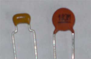
Epoxy Cap on Left, Ceramic cap on right.
These two types of components account for about 90% of the parts in the kit so we will talk about the other parts as we fit them.
Work through the parts list and mark off each resistor and capictor as you find them ,
If you have any problems
email me to start with 
Ok have a cup of coffle and a break and then we will move on to the next bit.
< Previous Next > Back to SW+ Project Build page