SW+ Project Build - Stage 4 The Product Detector/BFO & Crystal Filter
Build instructions by Paul M0BMN
< Previous Next >Stage 4 The Product Detector/BFO & Crystal Filter
Here we will be working on the second part of the receiver section first find the following part out ready to fit
Resistors
Only One in this stage
R1 which is 330 Ohm Marked Orange-Orange-Brown
Capacitors Next
| C12 | 270pf | Ceramic Disk marked 271J or 271 |
| C13 | 270pf | as above |
| C14 | 270pf | as above |
| C15 | 270pf | as above |
| C16 | LINK | Use a off cut of wire to fit here , C16 not used but needs linking |
| C17 | 68pf | Ceramic Disk Marked 68J or 68 |
| C18 | 150pf | Ceramic Disk Marked 151J or 151 |
| C104 | 0.01uF | Ceramic Disk Marked 103M or 103 |
| C105 | 0.01uF | as above |
Now The Semiconductors
Only two in this stage
D2 which is a Glass brown body Diode
U3 NE612 or NE602 8 pin IC and its 8 Pin Socket (Fit the socket first of course!)
Last parts
4 off Crystals Marked ECS V 8.00 -S (Yes i know you have five but this stage only needs 4 of them)
right off we go, we will fit the one resistor first
R1, look at the instructions that came with the kit for its location.(Check its value with your meter)
Now onto the Capacitors
start at C12 and work through till C105
Take note that C16 is now replaced by a link wire, just use a off cut from one of the other parts
Now you should have a board that looks like this
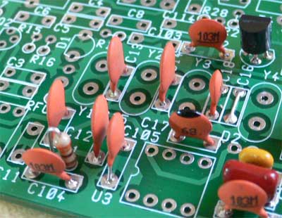
Note the wire link in C16's place
Now we will fit the Diode and The socket for U3
Make sure that you fit D2 the right way round!
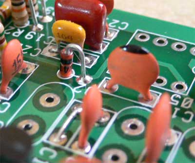 See the band on D2 is on top
Now fit the socket for U3 and then the crystals
The crystals can
be damaged by heat so don't take to long to solder these in, a few seconds at
most on each leg is all that you
want to spend with the iron, also don't use loads of solder, its not "Bigger
the blob better the job!" to much solder can cause a short between the
can and the leads on the top of the board, just be careful and all will be well,
if you want use your meter to
check for shorts by touching one probe to the top of the crystal and the other
to the pins on the crystal, you should not have a
short, if you do use solder sucker or wick to remover the crystal and then clean
it up with the wick and refit.
Our board should look like this now,
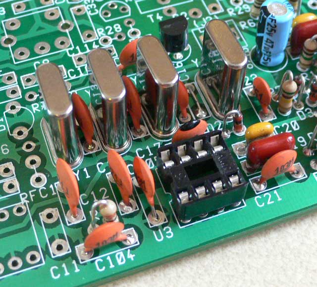
You can fit Chip U3 (NE612) if you wish now or fit it later.
Now one more stage left before we finish the RX section and start of the TX
< Previous Next > Back to SW+ Project Build page