SW+ Project Build - Stage 6 The Transmit Mixer and Driver
Build instructions by Paul M0BMN
< Previous Next >Stage 6 The Transmit Mixer and Driver
Well we have built the RX stage and if like me you have wired up the board so you could use it as a RX you now need to take off all those wires so we have just a PCB left. If you didn't wire up the board to power. phones and antenna then that's great your ready to go!
lets get the parts we need for this stage sorted
Resistors
| R19 | 1K Ohm | Brown- Black- Red |
| R20 | 22K Ohm | Red- Red- Orange |
| R21 | 10K Ohm | Brown- Black- Orange |
| R22 | 10K Ohm | as above |
| R23 | 22K Ohm | Red- Red- Orange |
| R24 | 500 Ohm | Blue Small Trim pot 3 legs |
| R25 | 2.2K Ohm | Red- Red- Red |
| R26 | 470 Ohm | Yellow- Violet- Brown |
| R27 | 10 Ohm | Brown- Black- Black |
| R28 | 51 Ohm | Green- Brown- Black |
Then The Capacitors
| C28 | 68pf | Ceramic Disk marked '68J' or '68' |
| C29 | 220pf | Ceramic Disk marked '221J' or '221' |
| C30 | 330pf | Ceramic Disk marked '331J' or '331' |
| C31 | 470pf | Ceramic Disk marked '471J' or '471' |
| C32 | 330pf | Ceramic Disk marked '331J' or '331' |
| C33 | 0.01uF | Ceramic Disk marked '103M' or '103' |
| C34 | 0.01uF | as above |
| C108 | 0.01uF | as above |
| C109 | 0.01uF | as above |
| C110 | 3.3uF | Elec Cap marked 3.3uF 50V |
| C111 | 0.01uf | Ceramic Disk marked '103M' or '103' |
| C114 | 0.1uF | Small Yellow Pillow Type Marked '104' |
and the semiconductors
| D11 | 7.5V Zen | In the bag with the wire you will find 2 diodes, One 7.5v |
| Q3 | 2N3906 | marked with its number |
| Q4 | 2N4401 | marked with its number |
| Q5 | 2N4401 | marked with its number |
| U5 | NE612 | marked with its number |
Inductors
| RFC2 | 6.8uH | In Bag with Zen Diodes Blue-Grey-Gold-Gold |
| T2 | 10.7MHz IF Transformer | Metal can with 5 pins and a large green slug |
| T3 | 10.7MHz IF Transformer | Metal can with 5 pins and a large green slug |
| T4 | See Note | Another wind it yourself coil its easy (see below) |
And finally that last Crystal (see i told you we would use it!) marked ECS V 8.00-S
Right Lets get on with it.
First the easy bit the resistors
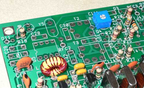
Here are all the resistors fitted
Now move onto the caps, another easy job
The only couple of points for you about this part is:
Make sure you fit C110 the right way round , the long lead goes into the hole on the board with a small + by it.
Also you may wonder where the hell does C109 go! well its not marked (or C108 ) on the silk screen or on Dave's instruction on page13. if you look on page 9 you will see a nice big layout drawing that shows where to fit it, C108 is just above C10 and C109 is just above C108 and to the left of U5.
Now The semiconductors
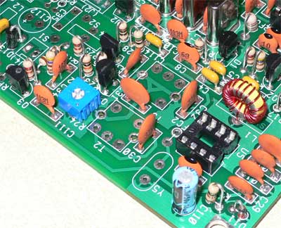
Don't forget to fit a socket now for U5
make sure you
fit the right transistor in the right place, and don't mix the zenner diode
with the other diodes in the kit
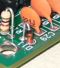
also make sure you fit D11 the right way round
Ok well done things are getting a bit tighter now don't you think? nearly done.
Now fit the inductors RFC2 , T2 & T3
While we have the soldering iron out fit the Crystal Y5 too.
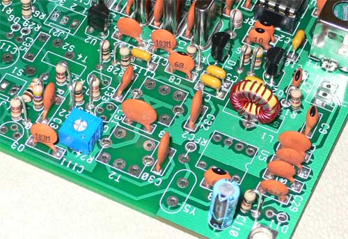
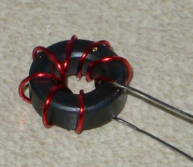
right now about that Toroid T4, its easy to wind, easier than that VFO coil you did.
Make sure you
use the gray core for this one and the instructions say cut four inch of wire
to wind it,
now if you have any wire left from when you wound the VFO coil use that , the
thicker wire and use about 6inchs ,if you have a little longer length than that
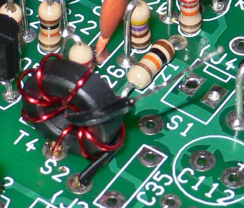
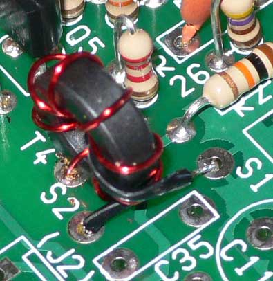
fine use it , wind 8 turns and strip and tin the ends, it should look like mine
below.
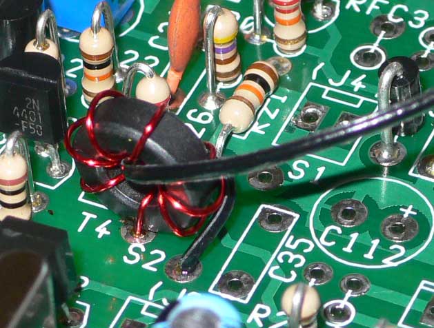
Now fit T4 as we did for the VFO coil BUT DONT CUT THE LEADS OFF YET
This is a transformer, so we have wound the Primary side only , we now need to wire the secondary side (that's easy)
Follow the instructions on page13, here are a few pictures of how i did mine
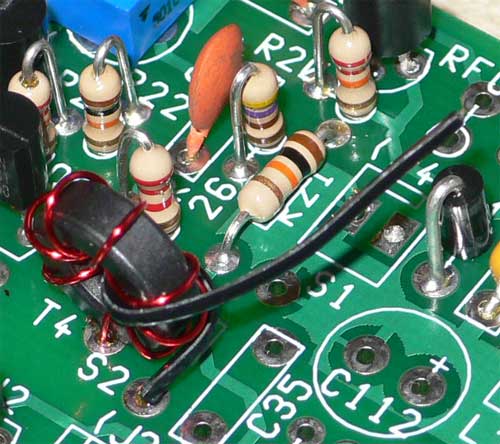
If your all done now trim the leads for T4
Well done that was the hardest part of the kit only a little bit more to do before we finish
< Previous Next > Back to SW+ Project Build page