SW+ Project Build - Stage 2 Melting solder for the first time
Build instructions by Paul M0BMN
< Previous Next >Stage 2 Melting solder the 1st time
Ok so i guess your ready to stick bits into your board and melt some solder.
we will follow the instructions so we will be looking at page 11 of the manual, we are told to start with fitting 4 parts and there is a picture to tell us were to fit them.
D13 IN4001 (large
black 1A diode)
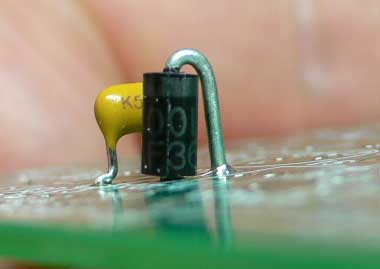
C113 0.1uF epoxy disk capacitor (This is a small yellow pillow shape device
with 104 printed on one side)
C102 0.01uF Ceramic disk (brown disk, marked 103M)
U2 78L08 8Volt voltage regulator/
Now make sure that we fit the diode the right way round!
Note the band
is on top!
also in the picture is the C113 captor (104 = 0.1uF)
Now a word on soldering, when fitting a device push it though from the top and bend the legs out a little to hold it in place for soldering, turn the board over and apply solder, make sure you read the soldering tips in the instructions if you are new to this.
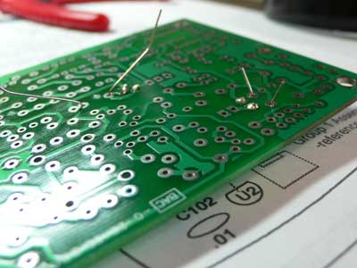
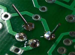
The first picture shows the wires bent to stop the device falling out during soldering, the second picture shows what the joints should look like after soldering and what they look like after you trim them.
When you fit the U2 Device (78L08) which is a 3 pin voltage regulator make sure you follow the outline on the PCB and push it down so about 4-5mm of lead is above the board, treat this part with extra care as its a intergrated circuit and could be damaged by to much heat when soldering or from static.
Well done, that's the first building stage over, we will now move onto the Audio amplifier stage which begins on page 12 of the manual.
< Previous Next > Back to SW+ Project Build page